
 Complaint

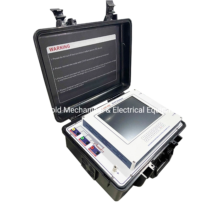
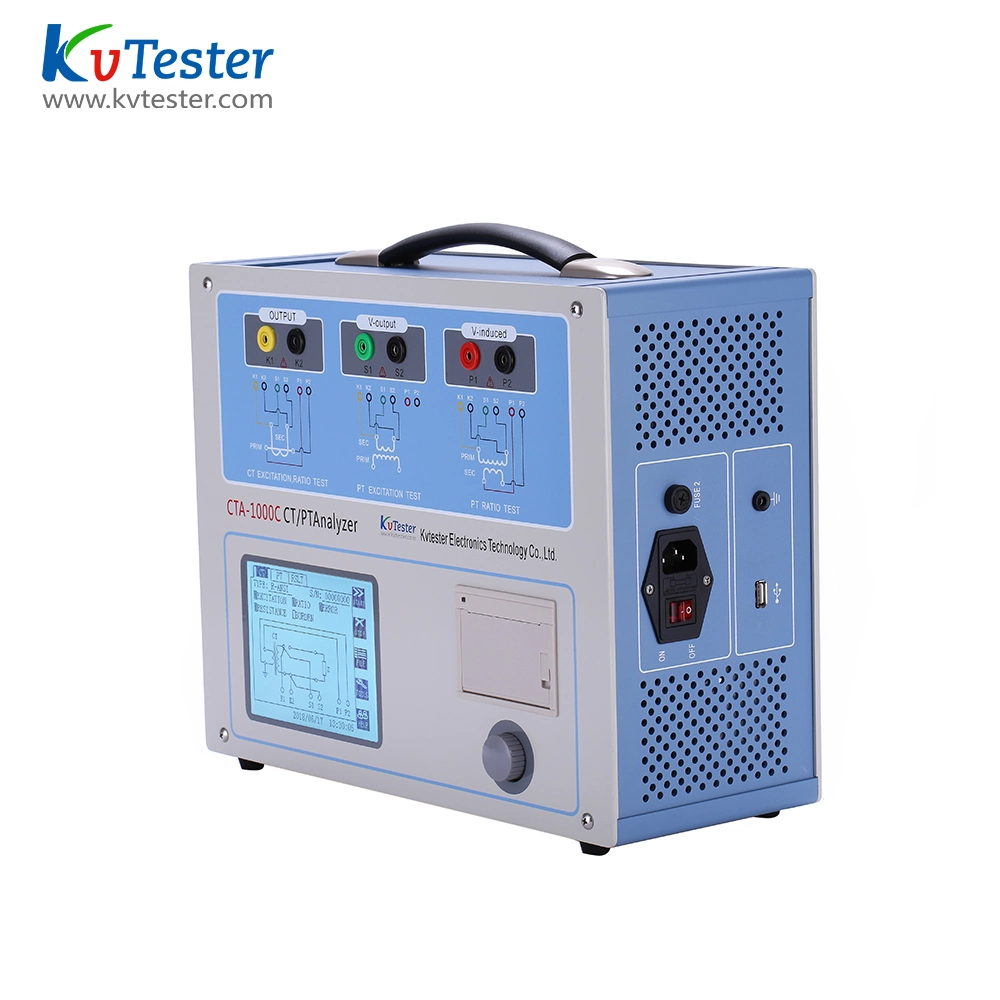
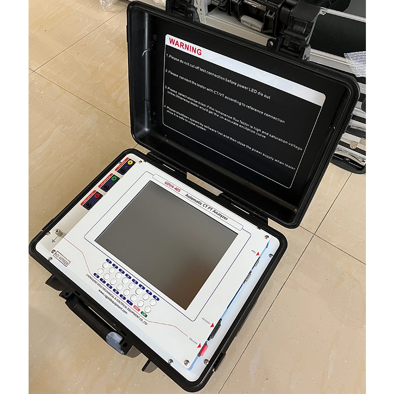
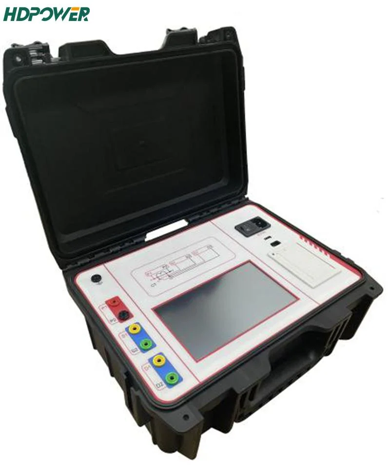
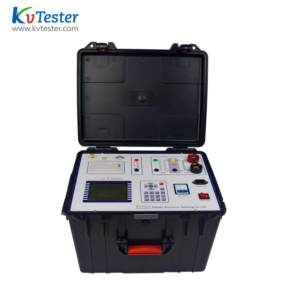
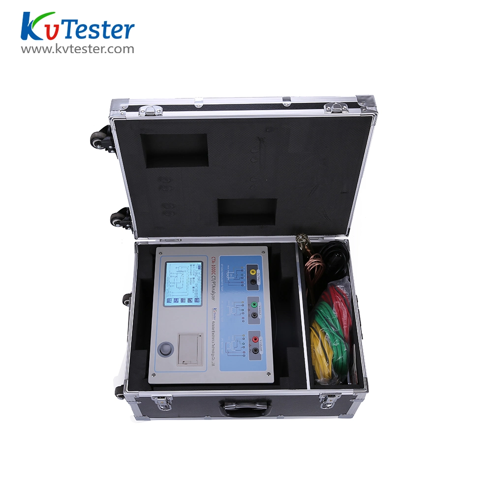
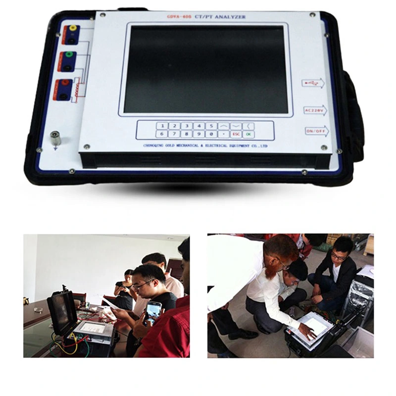
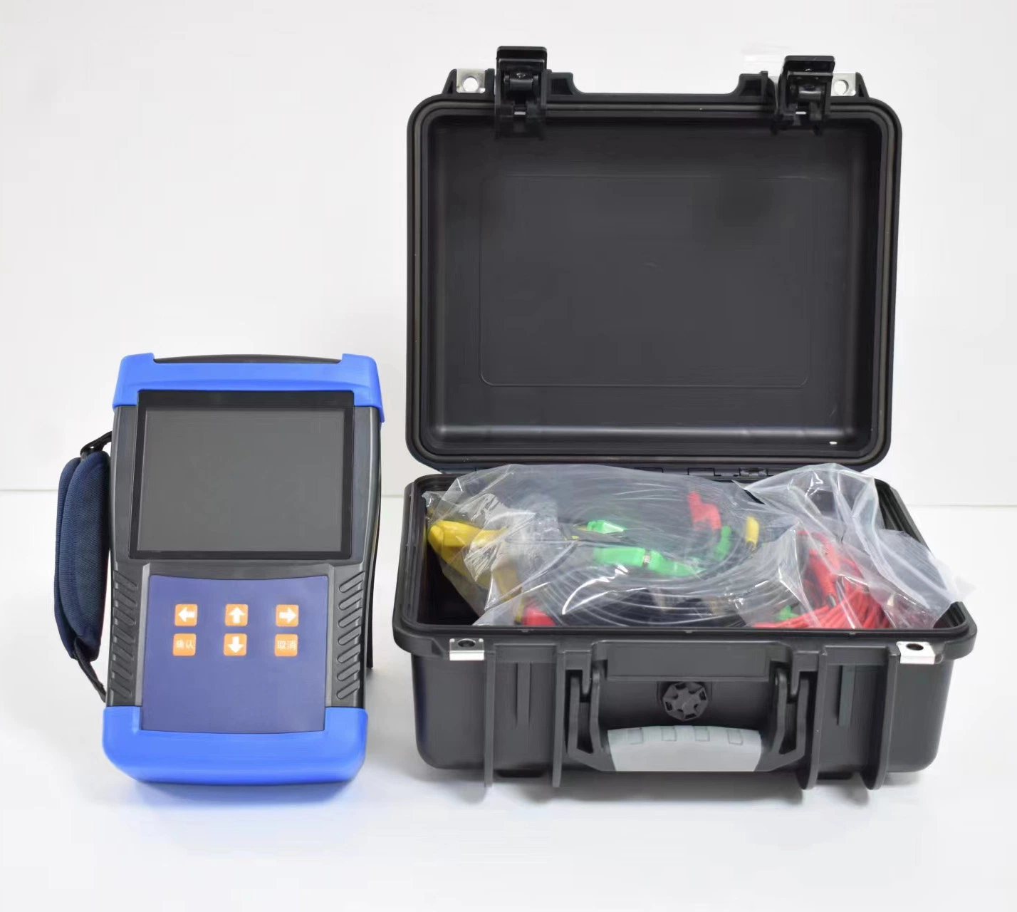
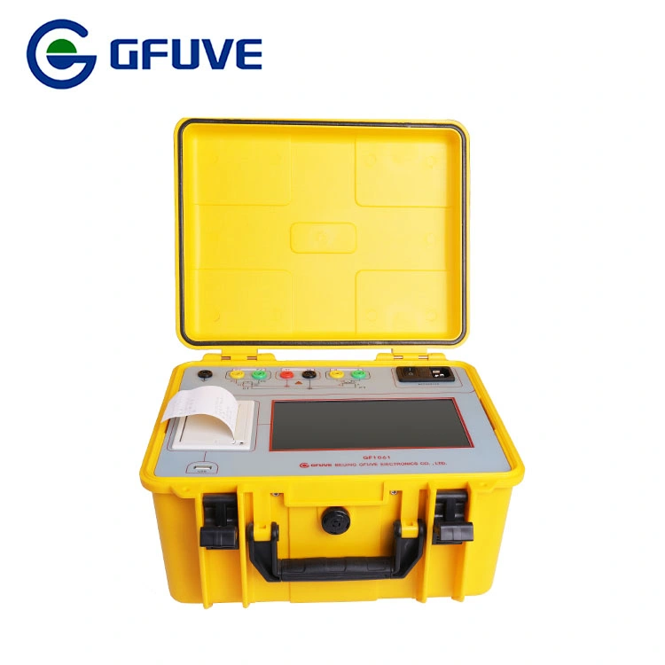
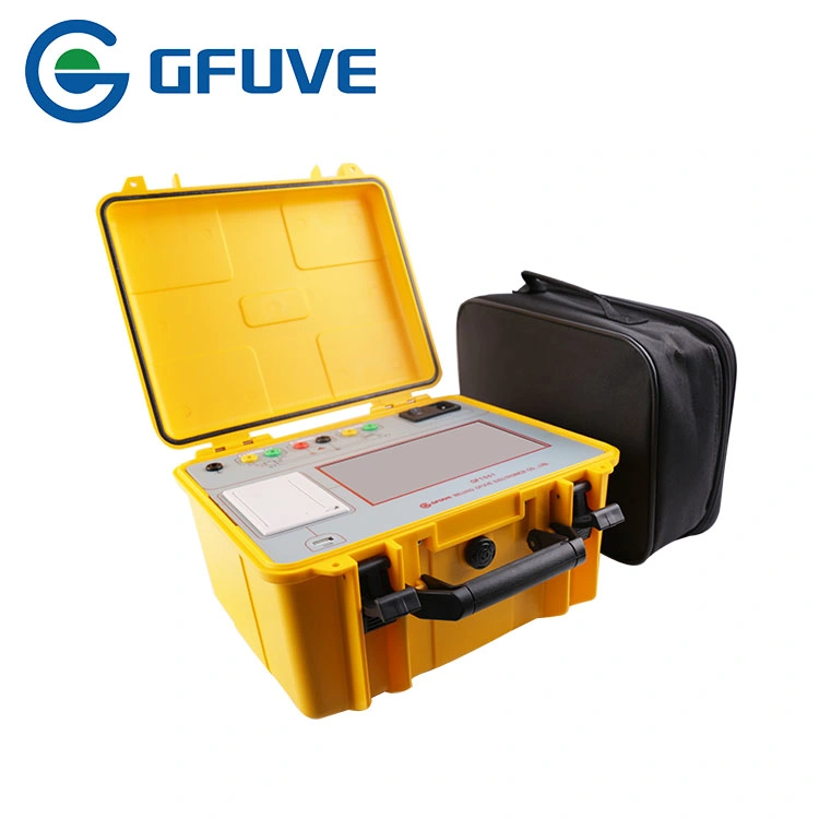
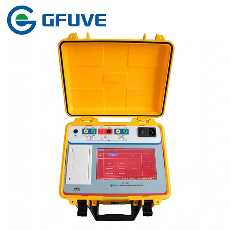
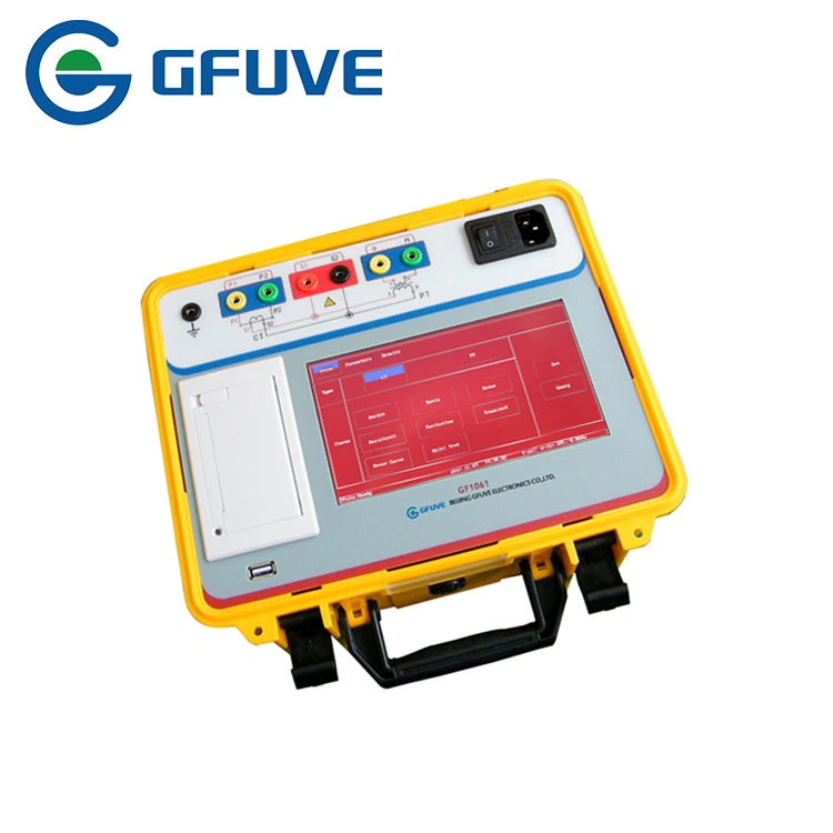
GF1061 portable CT PT analyzer is mainly used for field or lab testing, it can finish the measurements (M) and protection (P) class CT, PT and TYP class CT. Adopt 7 inch touch TFT LCD, self-equipped mini type printer supporting field printing; supporting to use USB flash disk to dump data. The CT PT Analyzer is the most complete and easy-to-use testing system for protection and metering CTs according to IEEE and IEC standards.
The CT Analyzer is the most complete and easy-to-use test system for protection and metering CTs according to IEEE and IEC standards. It combines the highest safety standards with CT test and assessment features. The CT Analyzer approach.
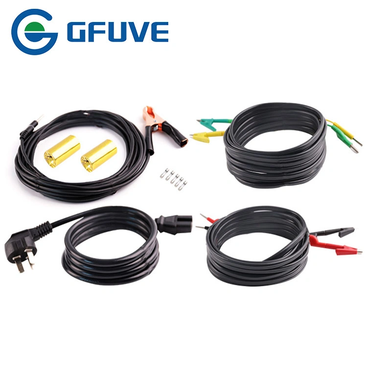
Before starting to work, clearly establish the responsibilities. Personnel receiving training, instructions, directions, or education on the CT Analyzer must be under constant supervision of an experienced operator while working with the equipment. The operator is responsible for the safety requirements during the whole test.CT Kneepoints up to 80kV CT grouped testing includes Demagnetization, Knee Points, Ratios, Saturation Curves, Winding Resistances, Polarities and Phase Deviation (on all taps of multi-ratio CTs) VT testing including Demagnetization, Ratio, Winding Resistance, Polarity and Phase Deviation.
| I. Current Transformer (CT) | II. Voltage Transformer (PT) |
|---|---|
| 1. Magnetization curve | 1. Excitation characteristic test |
| 2. Transformation ratio test | 2. Transformation ratio test |
| 3. Polarity | 3. Polarity |
| 4. 5% and 10% error curve | 4. Ratio error, phase error |
| 5. Accuracy limiting factor (ALF) | 5. Degauss |
| 6. Degauss | 6. Calculation of knee point value |
| 7. Ratio error, phase error | 7. Actual secondary load test (burden test) |
| 8. Automatic calculation of excitation knee point value | 8. Resistance test |
| 9. Actual secondary load test (burden test) | |
| 10. Resistance test | |
| 11. Secondary time constant (Ts) | |
| 12. Remanence coefficient (Kr) | |
| 13. Transient dimensioning factor (Ktd) | |
| 14. Peak instantaneous error (Er) | |
| 15. Magnetizing inductance (LU) | |
| 16. Instruments security factor(FS) | |
| 17. Composite error | |
| Electrical parameters | ||
|---|---|---|
| Accuracy | 0.05% | |
| Power supply | AC 220V±10% or AC 120V±10%, 50/60Hz or Battery | |
| Output voltage | 0-100Vrms | |
| Output current | 0-5Arms (20A peak-value) | |
| Output power | 0-400 VA (1500 VApeak) | |
| Automatic frequency variation range | 0.1-60Hz | |
| Equivalent excitation voltage | ≤5000V | |
| Accuracy | ≤0.5% | |
| Secondary winding DC resistance measurement | Range | 0.1-1000Ω |
| Accuracy | ≤0.05% | |
| Secondary actual load measurement | Range | 5VA-1000VA |
| Accuracy | ≤0.5%±0.1VA | |
| CT/PT phase error measurement | Accuracy | ±1min (typical) / 3 min (guaranteed) |
| Resolution | 0.1min | |
| CT ratio error measurement | Range | 1-50000 |
| Accuracy | ≤0.05% | |
| PT ratio error measurement | Range | 1-10000 |
| Accuracy | ≤0.05% | |
| Standards | ||
| Reference standards | GB1207-2006, GB1208-2006, GB16847-1997 IEC60044-1, IEC60044-6, IEC61869-2, ANSI/IEEE C57.13 | |
| Safety standards | GB 4793.1-2007 | |
| EMC | EMC standard 89/336/EEC | |
| FCC Subpart B of Part 15 Class A | ||
| IEC 1000-4-2 /3 /4 /6 | ||
| Mechanical parameters | ||
| Overall dimension (L x W x H) (mm) | 280 x 250 x 160 | |
| Weight (kg) | ≤4 | |
| Environmental conditions | ||
| Relative humidity | Relative humidity 5%-95% not condensing | |
| Operating temperature | -10°C to +50°C | |
| Storage temperature | -20°C to +70°C | |
| Altitude | ≤1000m | |